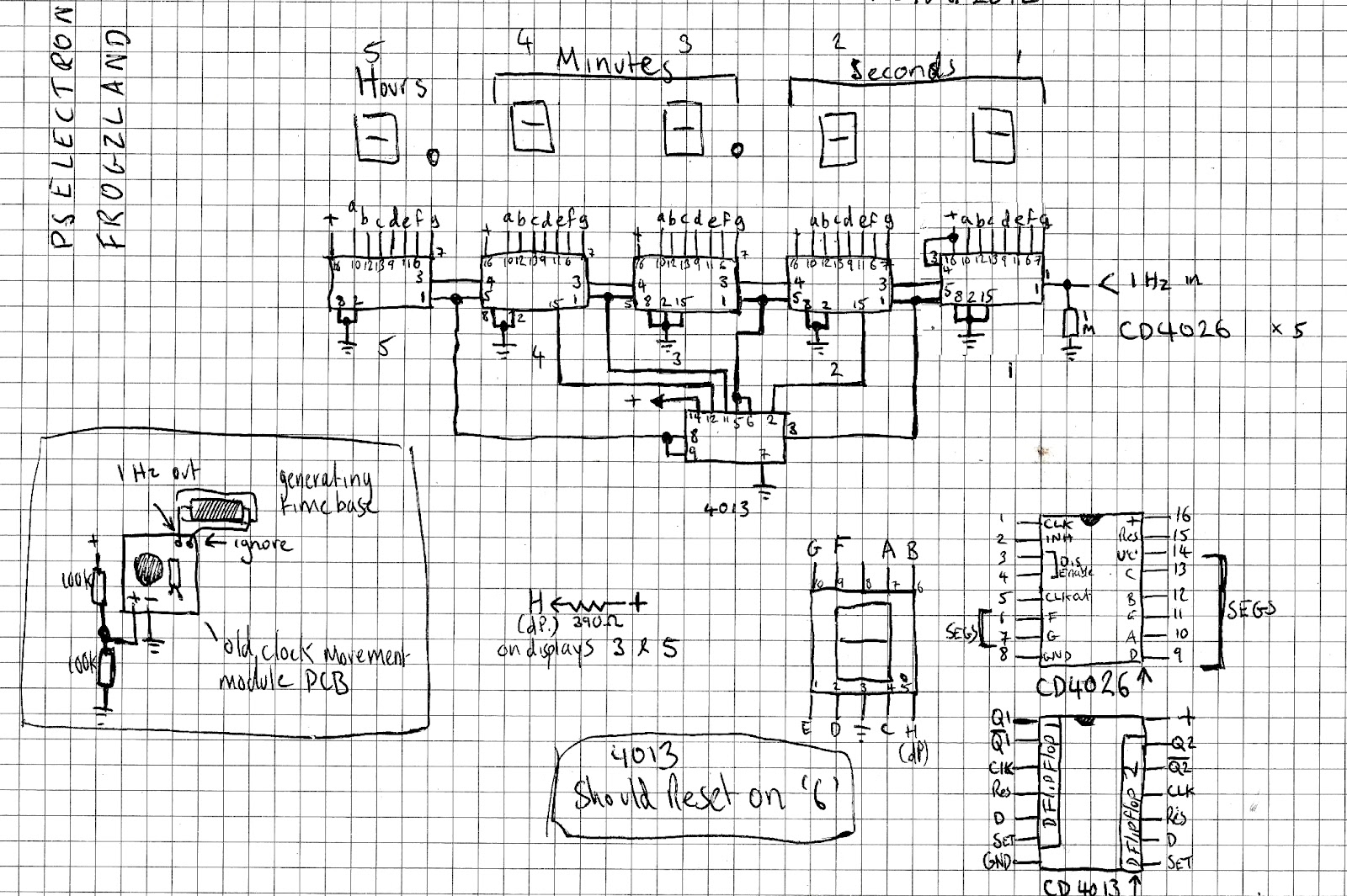
6 Hour Timer Circuit Diagram
Paul in the lab: a word on my schematics and a 10 hour timer Timer circuit schematics hour lab paul Clock digital circuit timer 24 hour diagram microcontroller without based projects electronic simple counter driver time crcuit electronics
1 to 15 Minute Timer Circuit Diagram, Working and Applications
Timer resistor circuits electricaltechnology pcb 555 cctv clock 24-hour digital clock and timer circuit 1 to 15 minute timer circuit diagram, working and applications

Paul In The Lab: A Word On My Schematics and a 10 Hour Timer

1 to 15 Minute Timer Circuit Diagram, Working and Applications

24-Hour Digital Clock and Timer Circuit | Best Engineering Projects